Tuesday, 27 April 2021

FHC resto nr. 126; Boot area wiring

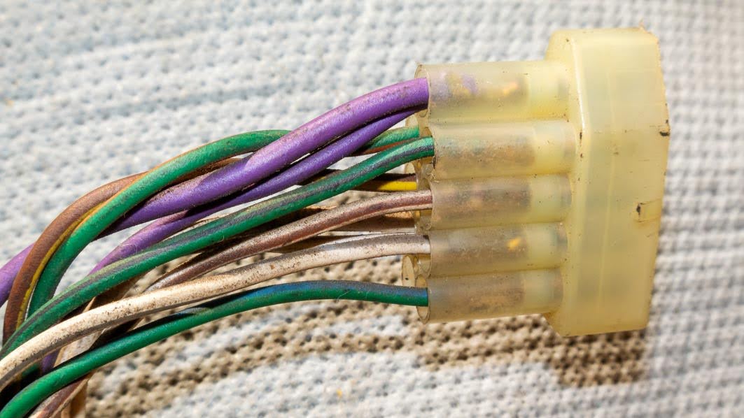
Over the past few days I have been busying myself with the finishing touches for the boot area wiring. This consisted mainly of cleaning the last connectors of the body harness and refurbishing the licence plate harness. With the (meanwhile) correct tools, the remaining connectors of both harnesses could be taken apart and cleaned. And were necessary they were replaced.


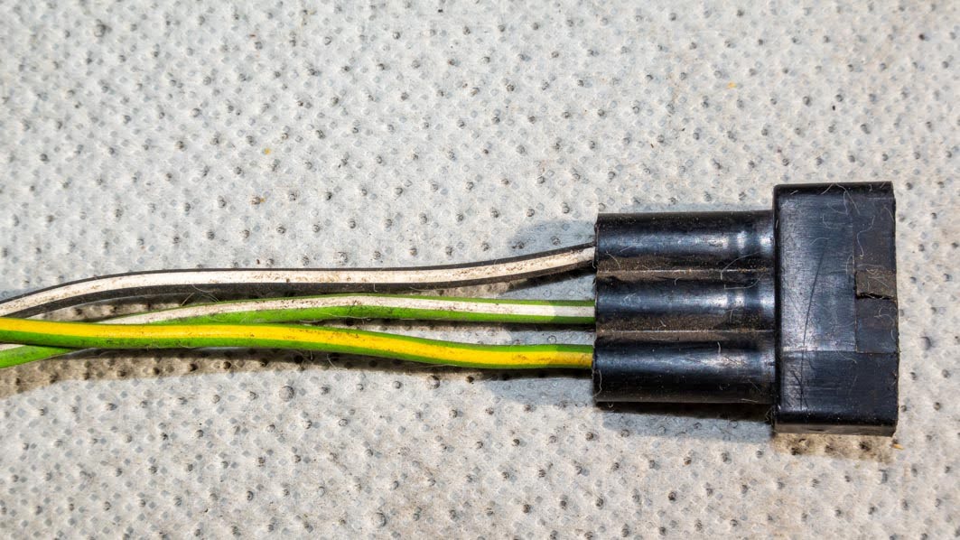
The same applied for the PVC cover of the number plate light harness. Removing the two pin connector block made this an equally easy job.


But of course something had to throw a spanner or two in 
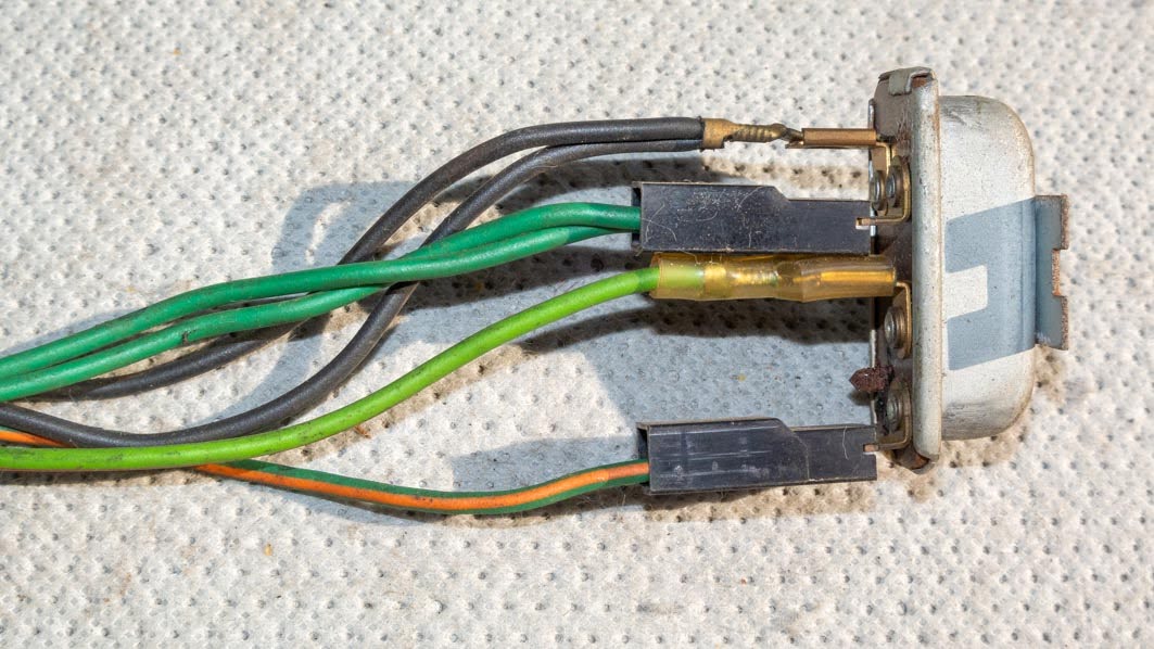
the works. In this case the boot light wiring and switch. First problem that arose were the wires that should go towards the switch and boot light. One connection (to the switch) was easy. But I couldn’t remember were the other (purple/red) wire should connect to. Luckily I had a TR7 at hand to check this. And that clearly showed why I couldn’t remember were said wire connected to!


So the connector in question was duly covered with a piece of heat shrink tubing.


And that brought me to the main issue. The boot light switch. A few months ago I had fitted a later model switch, because the early round type was no longer available. But that needed a different connector. This would be convenient as it would allow me to renew the PVC cover for these wires too! But while I was studying this area in the ’76 car and comparing it with the DHC I noticed something was “wrong”. Spot the difference!


Clearly there is no aperture for a light there. The opening where the boot light is situated on later cars, is far too big for the boot light that is listed in my parts manuals and that is fitted to my two other cars (1980 and 1981) The strange thing is that in the early (1975-1978) parts manuals there is no mention of this light not being fitted to early cars. It seems that the earlier cars didn’t have a boot lid light fitted. Which is pretty strange as the body shell has a small bracket welded in for an early (round type) switch. A quick search on the internet didn’t provide an unambiguous answer. But it looks to me that the very early TR7’s didn’t have a boot light fitted. And that is when I stumbled upon a correct early boot light switch for the cars bracket!


Not yet decided what to do here, though I am toying with the idea of fitting a period aftermarket light. Or fabricate an adapter plate to cover the larger hole in the boot lid and use the boot light I prepared earlier? Choices!
So I switched my attention to some vital parts for the rear light clusters. This meant searching through my stock of (used) bulb holders and giving the chosen ones a good clean:


And searching the stock in the attic for the corresponding bulbs. I bought these when I restored ‘t Kreng in the mid 90’s of the previous century. And so far none of them has failed. So no need to spend money on modern replacements.


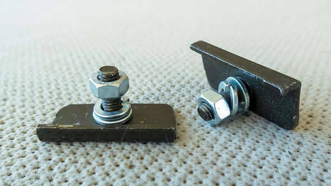
Final search was for a pair of bumper cover retainer plates (ZKC2251). These will be used to locate the base of the rear light covers to the boot floor.


And as I use this blog as a reference source when working on my cars, I thought it a good idea to draw a few simple diagrams, showing how the various wires connect to the rear light units and the tank sender unit.


To be continued … 

Saturday, 3 April 2021

FHC resto nr. 125; Gear lever gaiter finisher

Nearly finished another of the many very small jobs that take so much time to complete, but also are really good fun to do! In this case I had a go at remanufacturing the finisher/ferrule that sits in the top of the gear lever gaiter. The reason for this little project was the fact that this is how my best spare item looked, when I retrieved it from the parts stock; it just fell apart at the lightest touch!


And this is a part that hasn’t been available through the normal TR7 specialists for some time. Luckily the remains were large enough to provide me with all the measurements, necessary to reproduce a dimensional drawing of this finisher. Including some small personal touches of course!


The (AutoCAD) file was then used to produce a three dimensional model of the part, which in its final version looks like this on the computer screen:


This digital 3D model was then converted into a STL-file which in turn was used to produce the eventual finished product, using a friends 3D-printer. But before that we did a “standard plastic” test print, which turned out to be not entirely what I had expected. But that was my own fault. I had set the file’s resolution (FACETRES command in AutoCAD) at its lowest setting, were I thought I had it at its highest resolution setting. So very easy to rectify.
The final product was than printed using black ABS filament. The printed item already looks pretty good in real life. But it still needs additional treatment to give it a smooth and polished finish. Sadly getting the correct products is a bit of a problem with the current corona measures. But so far quite pleased with the result!


p.s. after I received the test print I found out that this part is still available (and rather cheap!), under its Spitfire part number (ZKC301). Though that looks like a remanufactured part, so probably poor rubber quality!?
 

Sunday, 14 March 2021

FHC resto nr. 124; Refurbishing facia harness RKC 4348

After taking lots of pictures of the facia loom last weekend, I took my time to carefully check all pictures. And when I was satisfied with the photographic records of the loom I could start with the actual job, starting with the main harness connectors. To remove these I had ordered a set of small connector removal tools. They were cheap and Chinese, and as such poor quality. But they did the job … sort off!


With the connector blocks removed, the initial impression of this harness was confirmed. All contacts were in very good condition. Though I gave them all a light polish just in case! After that the wires were cleaned with a rag moistened with petroleum ether. The connector blocks were treated to a hot bath in soapy water and a good scrub using an old tooth brush and a (trumpet) mouth piece brush. Which worked very well.


With everything cleaned it was time to put my photographic inventory to the test: adding the wires to the connector blocks. With the pictures on the screen in front of me, that was easy.


Plan was to remove the connector blocks for the facia switches next, but the tool decided it was enough. So far for cheap Chinese tools! As the connectors also looked in pretty good condition, I decided to just clean them. Though I might get back to these, once I have some better quality removal tools, which will be ordered soon. This left me with the removal of the harness’ wrapping tape and inspect and clean the remaining wires. Again no hidden horrors.


Remained the final job, wrapping the loom, using special non sticky PVC tape. A few hours this weekend well spent.


Saturday, 6 March 2021

FHC resto nr. 123; An inventory of RKC 4348


Started on refurbishing the wiring harnesses, which I will be using for the ’76 car, today. The plan was to start with one of the smaller harnesses, the facia harness (RKC 4348). Checking and cleaning the connectors and wires, and wrapping the harness with new wiring loom tape.
But first I wanted to document all connector blocks. This because the plan is to pull all connector blocks apart to inspect the crimped connectors and to give them a proper clean. And a photographic inventory should help to get all the wires back in their connector block in the correct position. So one of my cameras was put into action to document every connector from various angles.


That’s where it went wrong time wise. I had chosen the facia harness to start with, because it is a compact harness. So easy to work on. But despite its compact dimensions, it comes with a lot of connectors and a lot of wires. Which meant a lot of pictures. And by the time I had finished the photo shoot, and selected the pictures for the archive the afternoon had slipped by. But at least I now have a well-documented harness. The various connectors of which can be broken down in three main groups;

  1. The facia switches;
  2. The instrument panel;
  3. The main harness connectors.
Below a selection of the many pictures I took, starting with the connector blocks for the facia switches (from left to right);

The light switch:


The heated rear screen switch:


The fog light switch:


The hazard light switch:


A selection of the various connectors for the instrument panel.
To start with the low fuel warning unit and the wires that connect to it:


The 6 pin instrument panel connector:


The 12 pin instrument panel connector:


And finally the connectors to plug this harness
into the rest of the wiring of this car:


Hopefully I’ll be able to start dismantling the harness during the coming week. That’s the advantage of a small loom, I can work on it behind my desk!