Spent some more time on the main harness over the past week or so. But before starting with any physical work it was time for another record of the remaining connectors and relays (WARNING: picture heavy post 😏). Starting with the left hand side of the fuse box;

The connector for the right hand head light motor relay:


The connector for the head light flash unit (aka the Pektron unit):

The connector for the head light flash relay:


And from left to right one of the two connectors for the engine harness,
the head light motor circuit breaker and the hazard flasher unit:

The two connectors for the engine harness:


The inline fuse between the alternator and the hazard flasher unit. According to my Leyland wiring code table brown with a purple tracer should have something to do with the alternator regulator feed:

The original connectors for the radio, with the speaker wires in the background:

And the (unused) connector for the illumination of the automatic gear lever gate:

This area also contained the only modification added to this harness. And of course this modification was done with an infamous “fire starter” (maybe better known as a Scotchlock connector) Time for a proper repair, using a non-insulated fixed crimp connector and some heat shrink tubing:

Next inline were the connectors for the centre console and heater area. These are all positioned more or less on top of the heater unit:

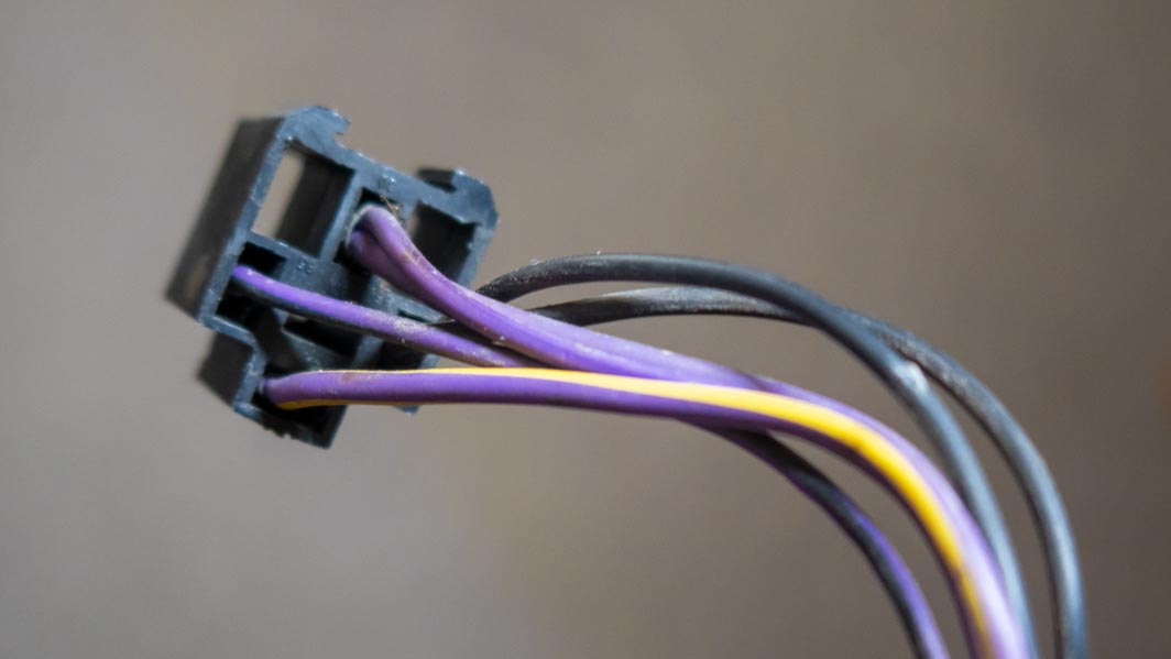
Black 3-pin connector with two wires connected:

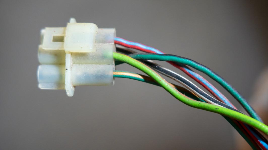
7-Pin connector:


4-Pin connector:

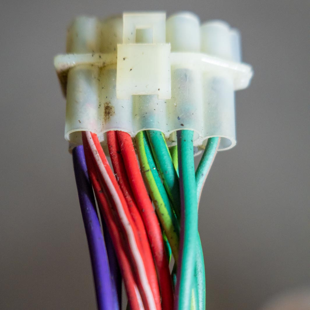
9-Pin connector with eight wires connected:


3-Pin connector with two wires for the heater unit:

5-Pin and a 1-pin connector:


2-Pin connector :

And various single male and female spade connectors:


The connectors for the instrument panel and steering column area;

The 5-pin connector for the windscreen wash/wipe switch:


The 9-in connector for the main/dip/flash and direction indicator switch:


The 5-pin ignition switch connector:


The 5-pin connector for the left hand door harness:


The four pin connector for the low coolant indicator unit. For the anoraks,
the unused hole in the connector block is blanked of with a plastic plug:


The connectors for the choke light switch:

The direction indicator flasher unit plus connector:

And finally a few details of the far end of the harness, the part supplying power to the coil and connecting the brake failure switch;

The beginning of the ballast wire (pink/white).
This is also the location of the harness I always use for connecting the power feed for the electronic ignition on my TR7’s:

And the wires for the coil (white/yellow and white/slate) plus the connector for the brake failure switch:

Next job will be cleaning and checking everything, including adapting the harness slightly for a feed for an electronic ignition module.