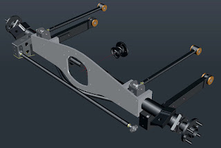
I should have been away on a walking trip to Süd Tirol now, but sadly we had to postpone that. Hopefully we will get another chance in the second half of September. Decided not to return to work immediately but start with some preparations on the cars. Over the past few months I have been toying with the various options for locating the anti roll bar to the new back axle set-up for 't Kreng. Initial plan was to use adapted upper links for all four parallel links, but that left me without mounting points for the anti-roll-bar. But there were a few available options, and the following options have been studied;
- The anti-roll-bar mounted against the rear bulkhead above the back axle, with drop links from the end of the anti-roll-bar to the back axle. This was hampered by lack of space between anti-roll-bar ends and the underside of fuel tank. Also problems with the routing of the exhaust;
- The same as above but with the anti-roll-bar mounted underneath the back axle. Here there were clearance problems with again the exhaust and the propshaft;
- The anti-roll-bar fitted behind the back axle, underneath the spare-wheel-well with mounting points either on top or below the back axle. In both cases there might be issues with the exhaust;
So in the end I decided to model the original lower links and rear anti-roll-bar in AutoCad to see if that set up could be adapted and used. But first I had to find a spare set of lower links, which in the end I found hidden somewhere in the shed. I got them many years ago from a friend, but never used them as they are of the earlier (4-speed) type, thus lacking the bump stop at the rear to prevent the axle from twisting upwards under power.
And after taking some measurements on one of the lower links and a spare anti-roll-bar I was able to model them on the computer ...
As you can see adapting the lower links to accept rose joints should be rather straightforward. This is of course helped by the fact that they won't get the loads from the springs as these are already fitted directly to the back axle. And with everything "fitted" it was time to load everything up in the main file to see how the clearance is. Especially the clearance between the anti-roll-bar and the back axle's stiffening plate, and between anti-roll-bar and the Panhard rod are crucial.
Clearly visible is the fact that clearance between anti-roll-bar and Panhard rod is fine, although I think in real life it might be a little less. Well pleased with that as it makes life a lot easier because I can work from a (well) known suspension set up, and don't have to try out all sorts of (custom ) made anti-roll-bars.
And with that sorted it is time to start with preparing the DHC for this year's edition of Club Triumphs 10 Countries Run, which will be run in early September.


No comments:
Post a Comment